¿QUÉ ESTÁS BUSCANDO?
Palabras clave objetivo: precio del techo de flujo laminar, eficiencia de filtración de aire de sala limpia, Filtro de ventilador FFU guía de la unidad
Un techo de flujo laminar basado en FFU ofrece una cobertura de clase ISO 5 mediante la disposición de módulos HEPA o ULPA con ventilador en una rejilla superior sellada, de modo que el aire filtrado se desplaza uniformemente hacia abajo a través de la zona crítica. El rendimiento depende menos de la clasificación de un solo FFU que de la cobertura del techo, la velocidad del flujo frontal, el control de fugas, el diseño del retorno de aire, las cargas térmicas y las obstrucciones.
Los proyectos de purificación del aire tienen éxito cuando el rendimiento del equipo, las instalaciones circundantes y el comportamiento diario se tratan como un solo sistema. Para los compradores que buscantecho de flujo laminar En cuanto al precio, la pregunta clave no es solo qué producto comprar, sino qué resultado debe mantenerse tras la instalación. La eficiencia de las partículas, el flujo de aire, la caída de presión, las fugas, la compatibilidad de los materiales, el acceso, la energía, las pruebas y la práctica del operador influyen en el resultado.
KLC Los enfoques internacionales para proyectos de techos de flujo laminar comienzan definiendo la aplicación, los contaminantes, el estado operativo, la presión disponible y la evidencia de aceptación. Este método basado en requisitos ayuda a evitar el sobredimensionamiento, el bajo rendimiento de los equipos y las deficiencias en la documentación.
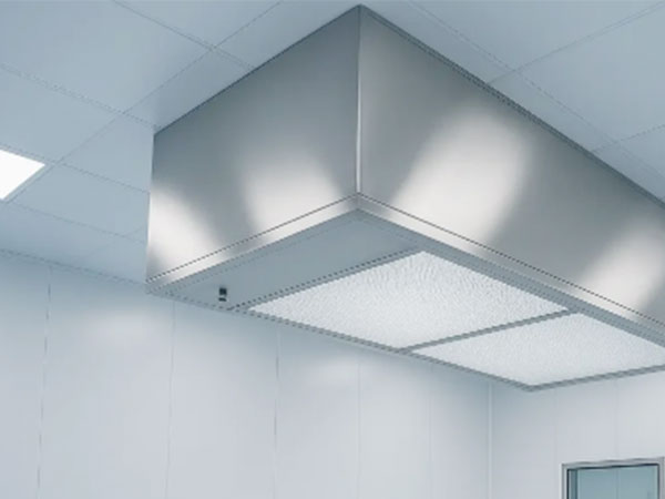
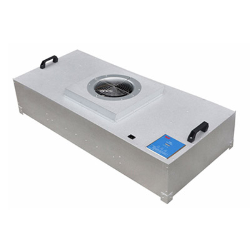
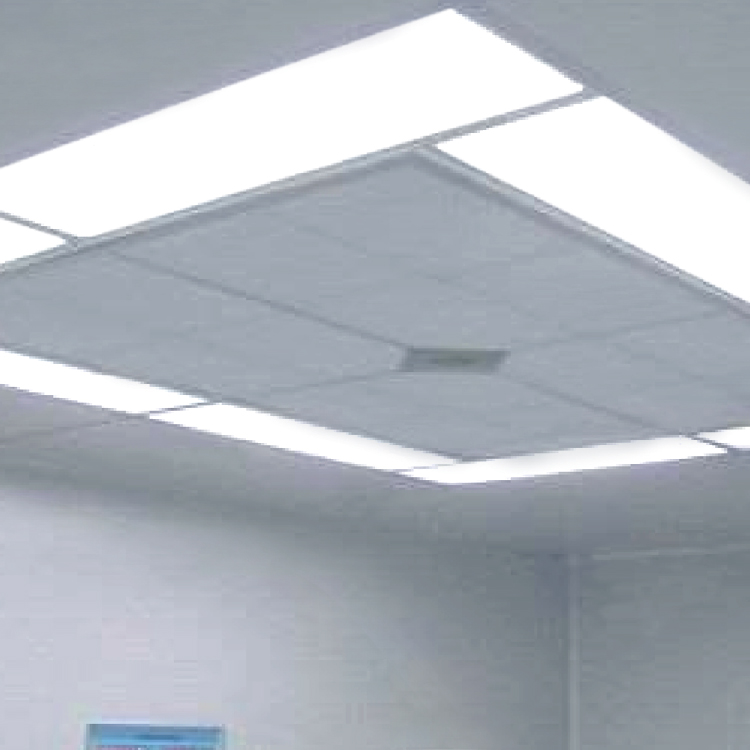
Una rejilla modular soporta unidades de flujo continuo (FFU), paneles ciegos, luces, rociadores e interfaces selladas sobre el proceso. Los compradores deben solicitar la norma de prueba, el punto de operación, la tolerancia y la documentación justificativa. Sin este contexto, las cifras de rendimiento, aparentemente precisas, pueden resultar engañosas.
Cada unidad de filtro de aire (FFU) proporciona flujo de aire local, mientras que los controles de grupo equilibran la velocidad y compensan la carga del filtro en todo el conjunto. Este requisito debe incluirse en la especificación aprobada, con una parte responsable y un criterio de aprobación/rechazo. Esto garantiza la objetividad en las decisiones de puesta en marcha cuando intervienen varios proveedores.
Los retornos de baja altura completan el flujo vertical y ayudan a prevenir la formación de remolinos alrededor de las máquinas y los operarios. En la práctica, esto implica que el equipo, el flujo de aire de la sala y el movimiento del operario deben revisarse conjuntamente. Un componente robusto no puede compensar las fugas por derivación ni un procedimiento incontrolado.
Comience por definir el largo y el ancho protegidos, luego reserve espacio para los servicios y determine la cobertura efectiva del filtro. La planificación del ciclo de vida debe tener en cuenta la carga del filtro, el consumo de energía, el acceso, los repuestos y el tiempo de inactividad. Estos factores suelen modificar la opción preferida, incluso cuando dos productos tienen un rendimiento inicial similar.
El caudal total es la suma del caudal activo de la unidad de flujo continuo (FFU) en el punto de funcionamiento seleccionado, no el valor máximo del catálogo. Su efecto debe comprobarse con el caudal y la carga previstos, ya que la especificación del catálogo puede no reflejar el rendimiento real tras la instalación.
Los análisis computacionales o los estudios de humo son valiosos cuando las líneas de llenado, los robots, los aisladores o las herramientas altas interrumpen el flujo. La planificación del ciclo de vida debe tener en cuenta la carga de los filtros, el consumo de energía, el acceso, los repuestos y el tiempo de inactividad. Estos factores suelen modificar la opción preferida, incluso cuando dos productos tienen un rendimiento inicial similar.
El costo está determinado por la cantidad de unidades filtrantes, el grado del filtro, el material de la rejilla, los controles, el monitoreo, el acceso a la instalación y el alcance de la calificación. Los diseñadores también deben confirmar cómo se inspeccionará, limpiará y restaurará después del servicio. El mantenimiento sencillo es fundamental para un control de la contaminación sostenido, no una conveniencia opcional.
Los motores EC/DC tienen un costo inicial mayor que los motores CA básicos, pero pueden reducir el consumo energético del ventilador y simplificar el equilibrado. La planificación del ciclo de vida debe considerar la carga del filtro, el consumo energético, el acceso, los repuestos y el tiempo de inactividad. Estos factores suelen modificar la opción preferida, incluso cuando dos productos tienen un rendimiento inicial similar.
La evaluación del ciclo de vida debe incluir filtros de repuesto, acceso seguro, tiempo de inactividad, alimentación eléctrica, puesta en marcha y futuras ampliaciones. En la práctica, esto implica que el equipo, el flujo de aire de la sala y el movimiento del operador deben revisarse conjuntamente. Un componente robusto no puede compensar fugas por derivación ni un procedimiento incontrolado.
Factor | Techo de FFU | Techo de suministro central |
Fuente de aire | Matriz FFU integrada | Pleno de presión de la unidad de tratamiento de aire central |
Equilibrio | Control de velocidad por unidad/grupo | Amortiguadores/equilibrio del sistema |
Escalabilidad | Alto | Medio |
Acceso al techo | Nivel de módulo | Nivel del plenum |
Mejor ajuste | Zonas críticas grandes modulares | Diseños permanentes estables |
La tabla sirve como guía para la planificación, no como sustituto de una evaluación específica del sitio. Las clasificaciones deben compararse con el mismo caudal de aire y según las mismas condiciones de prueba, y el rendimiento final debe verificarse tras la instalación. KLC puede adaptar los planos, materiales, filtros, motores, controles y documentación al punto de operación acordado.
Una solicitud de presupuesto útil debe incluir:
Elabore un mapa de la zona crítica real en lugar del contorno de la habitación.
Calcular el caudal de aire a la presión de funcionamiento del filtro cargado.
Coordinar la iluminación, la protección contra incendios, los servicios públicos y el acceso para mantenimiento.
Modelar las rutas de retorno y los efectos de las obstrucciones.
Especifique las pruebas de aceptación y los puntos de datos del sistema de control.
Solicite a KLC International que identifique las suposiciones y exclusiones en la propuesta. Una cotización clara debe distinguir entre las pruebas de fábrica y las pruebas en obra, los componentes suministrados y los trabajos de terceros, y las clasificaciones nominales de los valores garantizados.
Inspeccione el equipo a su llegada para verificar daños en el embalaje, identificación correcta, dimensiones, sellos, filtros, instrumentos y documentación. Durante la instalación, controle el polvo de construcción y proteja los medios sensibles. La puesta en marcha debe verificar la dirección y el volumen del flujo de aire, la presión diferencial, las alarmas, los enclavamientos, la seguridad eléctrica, el ruido (cuando corresponda) y el rendimiento de limpieza o captura especificado.
Tras la entrega, utilice un mantenimiento predictivo respaldado por inspecciones programadas. Monitoree la presión diferencial y el flujo de aire, investigue cambios anormales, proteja los filtros de repuesto y documente los reemplazos. Cualquier cambio en el medio filtrante, la velocidad del motor, la distribución de la sala, el funcionamiento de las puertas, el equipo de proceso o los productos químicos de limpieza debe dar lugar a una revisión de riesgos. Los equipos de servicio de KLC pueden ayudar a definir los repuestos y un plan de verificación adaptado a la aplicación.
Una propuesta fiable distingue entre afirmaciones y pruebas. Comience verificando que los planos coincidan con las dimensiones solicitadas, la dirección del flujo de aire, el acceso para el servicio, las instalaciones y las interfaces de instalación. A continuación, revise los informes de rendimiento del modelo probado, el método de prueba, el punto de operación, el estado del instrumento, el límite de aceptación y el resultado trazable. Un certificado de calidad corporativo puede generar confianza en los procesos del proveedor, pero no reemplaza los datos del producto ni la cualificación del sistema instalado.
Confirme también cómo se gestionarán las desviaciones y los cambios de diseño. El rendimiento puede verse afectado por diversos factores, como el material filtrante, los adhesivos, los motores, los sensores, los materiales del marco, los sellos y las plantas de producción. Para proyectos críticos, se requiere notificación anticipada de cambios, trazabilidad por número de serie o lote, registros de inspección acordados y un proceso definido para la gestión de no conformidades. La protección durante el envío debe formar parte del alcance técnico, ya que los pliegues aplastados, el gel dañado, los marcos deformados o la exposición a la humedad pueden invalidar un filtro que, de otro modo, cumpliría con las especificaciones.
La comparación comercial debe considerar el valor total entregado: equipo, flete, aranceles, instalación, energía, consumibles, validación, tiempo de inactividad, respuesta de garantía y vida útil prevista. Esto permite tomar una decisión más fundamentada que comparar únicamente el precio de compra y proporciona a los equipos de operaciones un presupuesto de mantenimiento realista.
Los errores más comunes son seleccionar basándose únicamente en la eficiencia nominal, ignorar la presión del sistema, considerar un certificado de fábrica como prueba del rendimiento en planta y posponer el acceso para mantenimiento hasta el final del diseño. Otro error es suponer que un mayor flujo de aire o una clase de filtro superior siempre garantizan la seguridad. Un flujo de aire excesivo puede generar turbulencias, aumentar el consumo de energía y alterar los procesos; una resistencia excesiva puede reducir el caudal suministrado. Un diseño equilibrado es más limpio y fiable.
KLC International recomienda documentar las bases del diseño y los criterios de aceptación antes de realizar el pedido. Este sencillo paso facilita la comparación entre proveedores y proporciona a los equipos de puesta en marcha un objetivo claro.
En la práctica, las normas utilizan conceptos de flujo de aire unidireccional; se prevé cierta perturbación local, la cual debe evaluarse.
En función del tipo de partícula a tratar y del riesgo del proceso, se puede seleccionar un filtro HEPA H13/H14 o un filtro ULPA U15/U16.
No siempre; la cobertura se diseña en función de la zona crítica, el flujo de aire objetivo, la distribución de la habitación y la clasificación.
Divida el caudal de aire total requerido entre el caudal de aire verificado por unidad y, a continuación, compruebe la cobertura física y la redundancia.
Cantidad de FFU, filtros de alta calidad, construcción de acero inoxidable, controles sofisticados, complejidad de la instalación y validación.
Las redes modulares suelen permitir la expansión si se ha planificado la estructura, la capacidad eléctrica, los controles y los retornos para ello.
Se utiliza un aerosol de prueba y un método de escaneo aguas arriba/aguas abajo de acuerdo con el procedimiento aplicable.
Sí. Crean estelas y pueden impedir que el aire limpio llegue al producto expuesto.
Resultan atractivas cuando la velocidad variable, el control de grupo, el menor consumo de energía o la menor generación de calor son factores importantes.
Como mínimo, se requieren recuentos de partículas que cumplan con los requisitos establecidos para el estado de ocupación especificado, respaldados por pruebas de flujo de aire e integridad del filtro.
¿Planea un proyecto que involucre un techo de flujo laminar? Comparta con KLC International la aplicación, las dimensiones, el flujo de aire, el rendimiento deseado, el entorno operativo, el mercado de destino y la documentación de prueba requerida. El equipo de KLC revisará las especificaciones, propondrá una configuración práctica y preparará un presupuesto que cubra el equipo, los filtros, los controles y las necesidades de verificación.
Solicite una revisión técnica o un presupuesto a KLC International para techos de flujo laminar.
Nota técnica: La selección final y el cumplimiento deben confirmarse con respecto a las normas, reglamentos, evaluación de riesgos del proceso y condiciones del sitio vigentes que sean aplicables al proyecto.



 Soporta red IPv6